Hbtorque
HB Torque EV Inverter Assembly Workstation | HB-F Lift-Assist System
HB Torque EV Inverter Assembly Workstation | HB-F Lift-Assist System
Couldn't load pickup availability
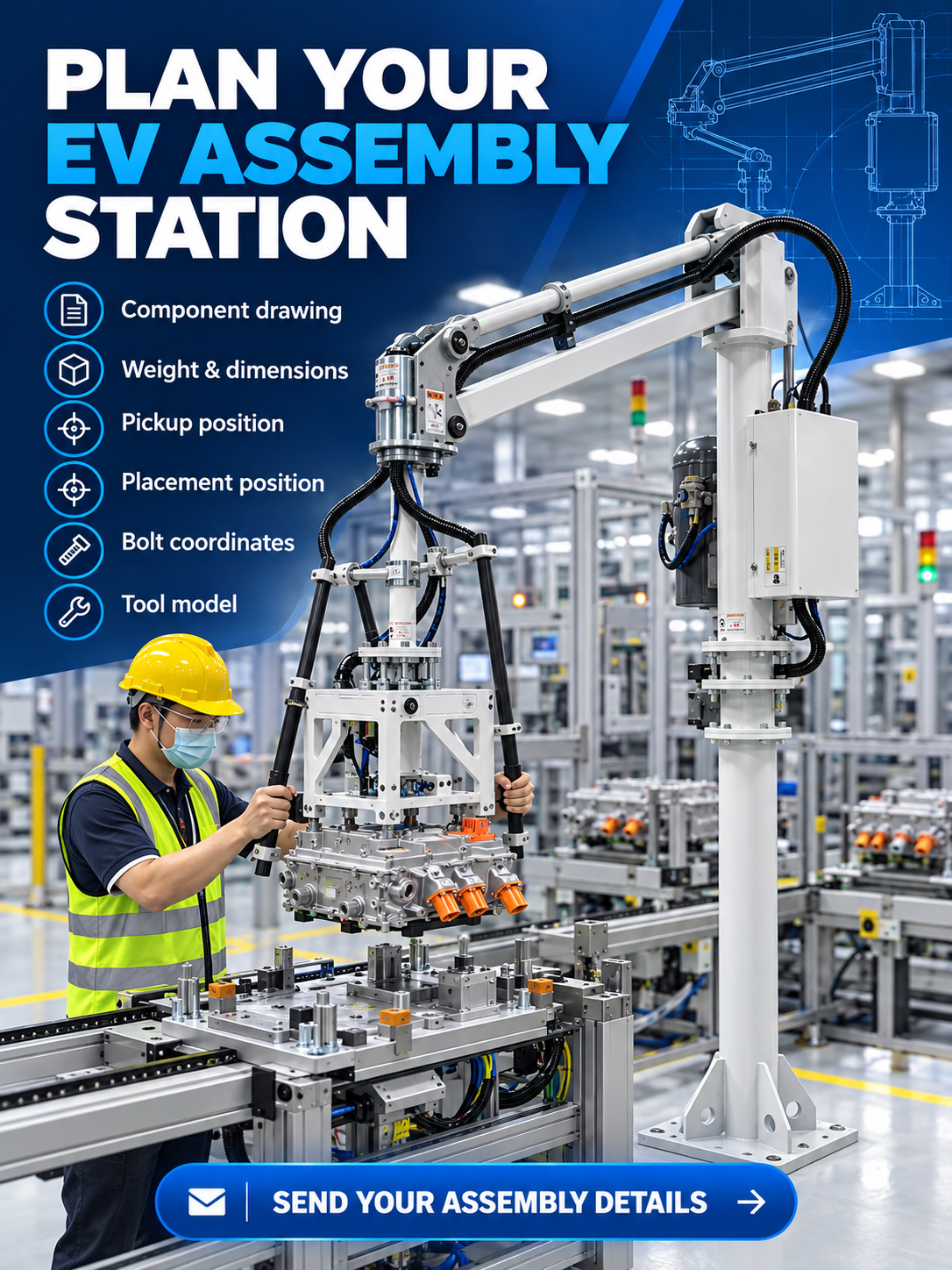
Planning an EV inverter handling and assembly station? Send the component drawing, weight and dimensions, approved lifting points, pickup and placement positions, bolt coordinates, tightening-tool model, target torque, and workstation layout. Request an EV assembly review.
HB Torque EV Inverter Assembly Workstation
The HB-F lift-assist workstation is engineered to help an operator pick, balance, transfer, and accurately locate an EV inverter, motor controller, or similar automotive component. The featured system combines a floor-mounted articulated pneumatic manipulator with operator handles and a component-specific rectangular fixture.
Typical Process Functions
- Engaging the inverter at approved lifting or support points.
- Balanced lifting and guided transfer between fixtures or stations.
- Controlled placement into an assembly nest or production-line fixture.
- Maintaining clearance around high-voltage connectors and sensitive surfaces.
- Evaluating fastening-tool support or process integration when required.
Tooling Built Around the Inverter
The handling fixture is not universal. HB Torque reviews the inverter enclosure, weight distribution, approved contact points, connector locations, restricted surfaces, pickup orientation, placement tolerances, and process sequence before defining the gripper or support frame.
- Part geometry: housing shape, dimensions, and center of gravity.
- Lifting points: approved mechanical engagement or support locations.
- Connector clearance: space around orange high-voltage connectors and interfaces.
- Placement alignment: relationship between the component, nest, and downstream assembly process.
Complete Workstation Scope
The engineered concept can include the support column, articulated balancing arm, pneumatic controls and service routing, operator handles, custom inverter fixture, and integration with the existing assembly station. Fastening support, torque-reaction hardware, verification, traceability, or line interfaces can be evaluated as optional process scope when the actual tool and fastening requirements are provided.
Information Needed for Selection
- Component drawing, weight, dimensions, and center of gravity.
- Approved lifting points and restricted contact areas.
- Pickup and placement positions, orientations, and required accuracy.
- Connector locations and required assembly clearances.
- Bolt coordinates, tightening-tool model, and target torque if fastening integration is needed.
- Workstation layout, cycle sequence, and site photos or video.
Frequently Asked Questions
Is the inverter fixture customized?
Yes. The fixture is developed around the real housing, lifting points, connector clearance, weight distribution, and placement sequence.
Does the standard system include a tightening tool?
The featured images show the inverter lift-assist and positioning system. Tightening-tool supply, torque-reaction support, verification, and integration must be defined separately during application review.
Can this station handle another motor-controller design?
Possibly, but differences in dimensions, lifting points, connectors, center of gravity, and placement interfaces must be reviewed before confirming common or interchangeable tooling.
Related EV Assembly Solutions
Explore Automotive & EV Assembly Solutions, read the EV inverter handling case study, compare the PRA Torque Reaction Arm, or send your assembly requirements.
Share